Load Capacity
Understanding the load capacity of a China Wave Spring Retaining Ring assembly requires calculations for both ring shear and groove deformation, with the design limitation being the lesser of the two. The load capacity formulas do not take into account any dynamic or eccentric loading. If this type of loading exists, the proper safety factor should be applied and product testing conducted. In addition, the groove geometry and edge margin should be considered. When abusive operating conditions exist, true ring performance is best determined thorough actual testing.
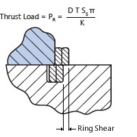
Ring Shear
 Although not commonly associated as a typical failure of China Wave Spring Retaining Rings, ring shear can be a design limitation when hardened steel is used as a groove material. Ring thrust load capacities based on ring shear are provided within our tables of standard rings. These values are based on a shear strength of carbon steel with the recommended safety factor of 3.
The thrust load based on ring shear must be compared to the thrust load based on groove deformation to determine which is the limiting factor in the design.
Nomenclature
PR = Allowable thrust load based on ring shear (lb)
D = Shaft or housing diameter (in)
T = Ring thickness (in)
SS = Shear strength of ring material (psi)
K = Safety factor (3 recommended)
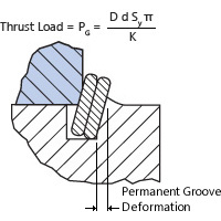
Groove Deformation
 Groove deformation is by far the most common design limitation of retaining rings. As permanent groove deformation occurs, the ring begins to twist. As the angle of twist increases, the ring begins to enlarge in diameter. Ultimately, the ring becomes dished and extrudes (rolls) out of the groove. As a conservative interpretation, the following equation calculates the point of initial groove deformation. This does not constitute failure which occurs at a much higher value. A safety factor of 2 is suggested. Ring thrust load capabilities based on groove deformation are provided within our tables of standard rings.
|
Typical Groove Material Yield Strengths |
|
| Hardened Steel 8620 | 110,000 psi |
| Cold Drawn Steel 1018 | 70,000 psi |
| Hot Rolled Steel 1018 | 45,000 psi |
| Aluminum 2017 | 40,000 psi |
| Cast Iron | 10-40,000 psi |
Nomenclature
PG = Allowable thrust load based on groove deformation (lb)
D = Shaft or housing diameter (in)
d = Groove depth (in)
SY = Yield strength of groove material (psi)
K = Safety factor (2 recommended)
Groove Radius
| Shaft or Housing Diameter | Maximum Radius on Groove Bottom |
| 1 inch and under | .005 Max |
| over 1 inch | .010 Max |
To assure maximum load capacity it is essential to have square corners on the groove and retained components. Additionally, retained components must always be square to the ring groove in order to maintain a uniform concentric load against the retained part. The radius at the bottom of the groove should be no larger than the table states.
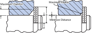
Retained Component
Maximum Chamfer = .375 (b-d)
Maximum Radius = .5 (b-d)
The retained part ideally has a square corner and contacts the ring as close as possible to the housing or shaft. The maximum recommended radius or chamfer allowable on the retained part can be calculated with the formulas to the left.

Nomenclature
b = Radial wall (in)
d = Groove depth (in)
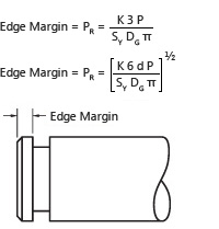
Edge Margin
 Ring grooves which are located near the end of a shaft or housing should have an adequate edge margin to maximize strength. Both shear and bending should be checked and the larger value selected for the edge margin. As a general rule, the minimum edge margin may be approximated by a value of 3 times the groove depth.
Nomenclature
z = Edge margin (in)
P = Load (lb)
DG= Groove diameter (in)
SY = Yield strength of groove material (psi)
d = Groove depth (in)
K = Safety factor (3 recommended)


Connect With Us